(artname: fdg0a011.EPS)

A VLAN is defined as a group of location and topology independent devices that communicate as if they are on the same physical LAN. This means that the LAN segments are not restricted by the hardware that physically connects them; the segments are defined by flexible user groups that you create using various network management tools.
With VLANs, you can define your network according to:
Implementing VLANs has three main advantages:
With traditional IP networks, network administrators spend much of their time dealing with moves and changes. If users move to a different IP subnet, the IP addresses of each device must be updated manually.
With a VLAN setup, if a device in VLAN 1 is moved to a port in another part of the network, you only need to specify that the new port is in VLAN 1.
With traditional networks, congestion can be caused by broadcast traffic that is directed to all network devices whether they require it or not. VLANs increase the efficiency of your network because each VLAN can be set up to contain only those devices that need to communicate with each other; therefore, limiting broadcast traffic to only those segments within the VLAN.
Devices within each VLAN can communicate only with devices in the same VLAN.
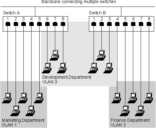
Figure 72 shows a network configured with three VLANs--one for each of the departments that access the network.
Figure 72. An Example of VLANs
 (artname: fdg0a011.EPS) |
The membership of VLAN 1 is restricted to ports 1, 2, 3, 4, and 5 of Switch A; membership of VLAN 2 is restricted to ports 4, 5, 6, 7, and 8 of Switch B while VLAN 3 spans both switches containing ports 6, 7, and 8 of Switch A and 1, 2, and 3 of Switch B.
In this simple example, each of these VLANs can be seen as a broadcast domain--physical LAN segments that are not constrained by their physical location.
The switch supports VLANs that conform to the IEEE 802.1Q VLAN standard. This specifies a standard VLAN implementation that allows operation of VLANs across a multivendor network. This provides the services of traditional port-based VLANs, but also allows true interoperability with other devices that support the 802.1Q standard. In addition, the switch supports GVRP, a protocol that automates the registration of VLANs across networks.
The switch supports up to 32 user-configured VLANs (including the Default VLAN (VLAN 1)). A port may belong to multiple VLANs. This is useful if devices on a LAN segment belong to multiple VLANs.
The switch assigns a priority of "0" to untagged frames. Otherwise, the priority specified in the VLAN tag of the frame at the originating end-station is used to determine which of two priority queues is used for frame transmission. Frames with a priority of 0 to 3 are transmitted as low priority. Frames with a priority of 4 to 7 are transmitted at high priority. The mapping from user priority to traffic class is defined in table 7-2 of the IEEE P802.1D standard
The switch supports IEEE 802.1Q standards-based VLANs. This standard describes port-based VLANs as well as the methods to propagate VLAN memberships across compliant devices using GARP VLAN Registration Protocol (GVRP). Each frame contains information about the VLAN. This information is contained in a 4-byte tag that is inserted into each frame. This tag contains information concerning the VLAN that the device belongs to.
GVRP automates the configuration of VLAN information at the switch. When using devices that support GVRP, VLANs will automatically be created on the switch based on information being passed across the network from other GVRP-enabled devices in frames referred to as GVRP PDUs. This further eases change and movement as the administrator does not need to make any configuration changes at the switch, the change will automatically be detected and the necessary VLAN port membership changes made by the switch.
The switch provides configuration options that allow the use of devices that do not support tagging or GVRP. With proper configuration, both "legacy" devices and devices that support tagging or GVRP may be used on the same network.
These configuration options are described in the following sections.
The Port VLAN ID (PVID) specifies a VLAN ID for all untagged frames received on the port. Only one PVID can be configured per port. This setting is used to determine to which VLAN the untagged frames belong as they enter the switch. The specific use of this value will be discussed later in this appendix.
The switch provides a feature that allows the automatic propagation of VLAN membership information across the network. This feature is facilitated by a new protocol called GARP VLAN Registration Protocol (GVRP) that is defined as a part of the IEEE 802.1Q standard. GVRP registration messages (PDUs) are sent across the network and received by GVRP-enabled devices (switches, adapters, and so on). This protocol allows devices to automatically join and leave VLANs. An advantage of this is that if a user moves from one network connection point to another, you would not have to manually reconfigure the switch ports to add the new switch port to the VLANs that the user belongs to.
GVRP messages are sent across the network with a group address of 0x0180C2000021. The GVRP PDUs use the the same DYAP/SSAP as Spanning Tree BPDUs. Older network analyzers often interpret these GVRP PDUs as Spanning Tree BPDUs. The switch allows you to disable the GVRP function on a switch basis or on an individual port basis.
Two VLAN types, static and dynamic are associated with the switch. As the network administrator, you can manually configure static VLANs. Dynamic VLANs are created on the switch as a result of GVRP registration messages. Consequently, a dynamic VLAN is automatically removed from the switch if it is no longer being used by other devices in the network. You can convert a dynamic VLAN to a static VLAN. Once this is done, the VLAN will remain configured on the switch until you remove it.
For each static VLAN configured on the switch, you can define the mode of participation for each port. There are three modes of participation:
When a port is configured to be included in a VLAN, the port is always a member of the specified VLAN. This is similar to port-based VLANs from other legacy products. VLAN membership of these ports will propagate across the network if GVRP is enabled. Ports should be included in a VLAN whenever VLAN membership of a port is desired to be guaranteed.
A port that is configured to be Autodetected does not initially belong to the given VLAN. However, the port may join the VLAN if a GVRP PDU is received on that port declaring membership in that VLAN. Ports may be left in Autodetect mode if the devices on the segment connected to the port all support GVRP and thus will register their VLANs with the port.
A port that is configured to be excluded is prevented from being a part of the specified VLAN. You can disable GVRP on a specific port or set of ports to ensure that they never join a VLAN by receiving and propagating GVRP PDUs.
The following section will discuss some common network configuration scenarios and how the switch should be configured to ensure proper operation.
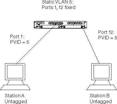
Figure 73. Untagged device to untagged device configuration
 (artname: fgb1a003.EPS) |
This configuration consists of two untagged "legacy" devices connected to the switch. In order for these devices to communicate, they must be members of the same VLAN. In this case, the PVID of the ports that the devices are connected to must be set to the VLAN that the devices are members of. In order to set the ports PVID, a VLAN must first be created with this VLAN ID. Additionally, both ports must be configured to untag frames for this VLAN.
After this configuration is complete, the frames from Station A will arrive at Port 1 untagged, and will then be tagged internally to the switch with the PVID (VLAN 5). These frames will be sent to port 12 which is a member of the same VLAN. Because the port is set to untagged frames for this VLAN, the tag will be removed and the frame sent to Device B untagged.
 (artname: fgb1a004.EPS) |
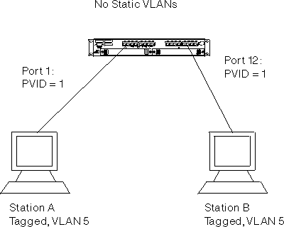
In this configuration, both devices support tagging and GVRP. Both devices are configured to transmit tagged frames for VLAN 5. GVRP must be enabled for the switch and for all ports which must participate in GVRP.
When Station A attempts to communicate with Station B, VLAN 5 (that Station A is a member of) is registered at Port 1 by GVRP. Likewise, Station B registers its membership with VLAN 5 on Port 12. Note that this VLAN will be dynamic because the network administrator has not explicitly configured the VLAN on the switch. Frames arrive at Port 1 from Device A, tagged for VLAN 5. These frames are forwarded to Port 12. The frames will be transmitted out of Port 12 tagged for receipt at Station B. Note that all frames in dynamically-created VLANs are transmitted as tagged.
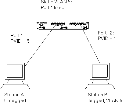
Figure 75. Untagged device to 802.1Q compliant device (tagging and GVRP) configuration
 (artname: fgb1a005.EPS) |
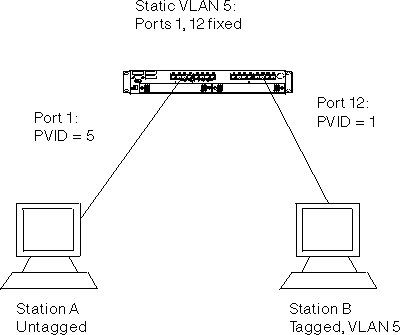
In this configuration, an untagged device, Station A, is attempting to communicate to a tagged device that is a member of the same VLAN. The network administrator first statically creates VLAN 5 on the switch to include Port 1 in this VLAN. Port 1 is configured to transmit frames untagged in VLAN 5 because Station A cannot comprehend tagged frames. Port 1 is configured with a PVID of 5 to ensure that untagged frames received on that port are assigned to VLAN 5.
Station B is also assigned to VLAN 5, and because it supports both tagging and GVRP it will automatically register its membership to VLAN 5. Because Station B resides off of Port 12, Port 12 must be configured to be either autodetected or always included in VLAN 5. Port 12 may be configured to transmit frames as either tagged or untagged because Station B is capable of handling both.
Frames from Station A arrive at Port 1 and are tagged with a VLAN ID equal to the PVID of Port 1 (VLAN 5). The frames are then switched to Port 12, where they are transmitted out of the switch either tagged or untagged, as configured. On the return path, frames tagged with VLAN 5 will arrive at Port 12, and will be received since the port is a member of VLAN 5. The frames will be switched to Port 1, and will be transmitted as untagged, as specified by the configuration of that port in that VLAN.
If any devices on a link cannot handle tagged frames, it would be best to configure the port to transmit frames as untagged in any VLAN in which those devices participate.
Figure 76. Untagged device to 802.1Q-compliant device (tagging only) configuration
 (artname: fgb1a006.EPS) |
The primary difference in this configuration is that Station B supports tagging, but not GVRP. As a result, VLAN membership information will not be propagated from Station B to the switch. Therefore, the network administrator must configure Port 12 to always be included in VLAN 5. If this is not done, Station B's frames will be dropped as they are received at the switch because the frame's VLAN tag does not match the port's VLAN membership set.
Once this configuration is complete, data flows as in the example above.
All addresses in the network should be unique to ensure proper communication.
The 8275-416 allows you the flexibility of configuring VLANs with identical port memberships. However, duplicate VLANs can unnecessarily waste VLAN entries and be an indication that the network design needs to be reconsidered. Too many duplicate VLANs may also lead to an oversubscription of switch resources.
The 8275-416 always guarantees resources for all 32 ports in the Default VLAN (VLAN 1). Up to 31 additional VLANs may be configured or registered with the switch, with certain restrictions.
In a switch with no feature modules (that is, with only the 16 base ports which may potentially be members of any VLAN) up to 10 ports may be included or autodetected in each of the 31 available VLANs. Phrased alternatively, the switch supports 310 individual instances of port VLAN membership distributed across non-Default VLANs in whatever fashion you choose. You can choose a configuration that "oversubscribes" the switch resources. However, unpredicted results may occur. You will be notified of potential oversubscriptions by the terminal interface message Operation succeeded. WARNING: Resources exceeded! A similar message appears if you are using the Web interface to configure your switch.
Oversubscription of switch resources due to dynamic VLAN registration cannot be predicted. Therefore, oversubscription will only be indicated during configuration if the number of statically included instances of port VLAN membership exceeds the threshold of 310.
The following configuration example indicates an acceptable configuration
for an 8275-416 with no feature modules:
Table 16. Acceptable VLAN configurations with no feature modules
| Configuration | Non-Default VLAN Port Instances |
|---|---|
| 16 ports in Default VLAN (VLAN 1)* | Not counted |
| 16 ports each in 2 other VLANs * | 32 |
| 10 ports each in 12 other VLANs | 120 |
| 8 ports each in 16 other VLANs | 128 |
| 9 ports each in 1 other VLAN | 9 |
| * Duplicate VLANs | Total 289 |
As the Table 16 shows, port membership can be distributed in many ways across many VLANs, and still not exceed the limits of the switch.
The two feature modules on the 8275-416 together have the same restrictions as the base ports of the switch. The addition of feature modules does not increase the number of non-Default VLAN port instances that can be supported by either the base ports or the two feature modules together. However, the addition of feature modules does double the number of non-Default VLAN port instances that can be supported across the entire switch, with 310 port instances distributed across the base ports and 310 port instances distributed across the feature module slots.
The limitation only exist for the number of ports used in either the top or bottom of the switch. There is no limitation using base ports and feature module ports in the same VLAN.
Although duplicate VLAN configurations can waste switch resources, there are some instances where they are useful. For instance, security concerns may be addressed by having devices on the same LAN segments belonging to different VLANs, but the VLANs having the same port membership. Another use for duplicate VLAN configurations would be if a switch is placed in the core or in an intermediate level of a network. The 8275-416 functions best as an edge device as opposed to as a core switch.